

The automotive terminal connector is a critical component in the automotive wiring harness field. And as an important node, directly affects the transmission of signals and power through the connector. In recent years, China’s automotive industry has experienced rapid development. Improving the field of automotive components, affecting the reliability and refinement of automotive connectors.
The significance of automotive terminals as a power transmission standard for automotive connectors cannot be ignored. By summarizing the problems encountered in using terminals in the past, several factors affecting the transmission capability of the terminals have been found. Including the material of the terminals, the design structure, the surface quality, and the crimping of the terminals.
Contents
I. Terminal Material
Considering functional and economic requirements, brass and bronze are currently used for terminal products in the domestic connector industry. Based on the differences in characteristics between the two materials, brass generally exhibits better conductivity than bronze under normal circumstances. But bronze has superior elasticity compared to brass. Considering the structural differences between pin and socket terminals. Pin terminals generally prioritize brass, offering better conductivity. Socket terminals typically have an elastic structure. And while meeting the conductivity requirements, bronze is usually chosen to ensure the reliability of the shrapnel of the terminal.
However, bronze may no longer meet the requirements for socket terminals requiring strict conductivity. In such cases, the common practice is to use brass for socket terminals as well. Considering the poor inherent elasticity of brass, a rigid support structure is added to the elastic structure to enhance the terminal’s elasticity, as shown in Figure (1).

Figure (1) shows that the terminal structure with rigid support is widely used in the connector industry. The improvement provided by the rigid support structure greatly enhances the positive pressure on the conductive contact surface and increases the conduction reliability of the product.
II. Design of the Structure
The design of the structure is essentially dependent on the premise of saving costs. To design both to minimize the expenditure of raw materials. And to maintain the power transmission of the terminal. So difficult to increase, like the connector terminal is most likely to affect the power transmission part is its “bottleneck” mechanism. The bottleneck refers to the terminal conductive surface of the smallest cross-section of the structure. The structure directly determines the terminal’s current-carrying capacity, terminal expansion diagram as shown in Figure (2).
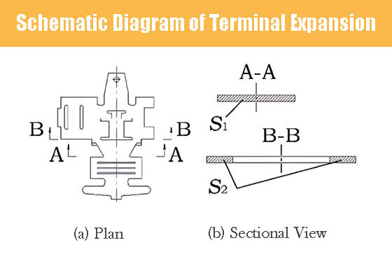
As can be seen from Figure 3b, the cross-sectional area of S1 is larger than that of S2, so compared to S1, the cross-section B-B is a bottleneck. In the design process, this cross-section must meet the conductive requirements of the terminal.
III. Surface Coating
Tin plating is a commonly used electroplating process for terminals. However, this process has the following disadvantages: Firstly, heating the tin coating to high temperatures or prolonged storage (even at room temperature). It can reduce its solderability and increase contact resistance. This phenomenon is mainly attributed to the protective effect of intermetallic compounds formed between the plating layer and the metal. Secondly, the contact material of the terminal plating has a higher surface friction than the plated metal. Resulting in a higher insertion force required for the connector. This defect is particularly noticeable when using multi-wire connectors. Therefore, when electroplating multi-wire connectors, it is advisable to choose new electroplating processes that reduce the insertion force of the connectors. Currently, gold plating is considered to be a favorable electroplating process.
From the point of view of microphysics, the surface of any smooth object is rough and uneven. So the contact surface of the terminal is not surface contact, but point contact one by one. In addition, the general metal surface is covered with non-conductive oxide film and other kinds of film layers. Thus, within the actual contact surface, only a tiny part of the film layer can be pressed through or voltage breakdown. Only in these areas can true electrical contact be achieved, and we refer to these contact points as “conductive spots.” The majority of contacts occur through the contact of the coatings. Thus, when current flows through the interface of two contact parts, the current will be concentrated through these tiny conductive spots, resulting in the contraction of current lines near the conductive spots. This leads to an increase in the path length through which the current flows. A reduction in effective conductive area, and the occurrence of localized resistance, known as “contraction resistance.” Improving the smoothness of the terminal surface can also enhance the transmission performance of the terminal.
Currently, the standards for coating quality inspection include ① Coating thickness inspection. This method involves judging the quality of the coating by checking its thickness. ② Conducting corresponding salt spray tests for inspection.
IV. Positive Pressure of Terminal Spring
The positive pressure of the connector terminal refers to the force exerted on the contact surface of the connector pin terminal and socket terminal, perpendicular to the contact surface. It is an important indicator that affects the performance of the connector. This factor directly influences the insertion force and electrical performance of the terminal.
In the process of using the terminal, the main problem is the unstable control of the insertion force between the terminal and the terminal. It is caused by the instability of the positive pressure of the terminal shrapnel, which leads to the increase of the contact surface resistance of the terminal and the temperature rise of the terminal. Also a series of problems such as ablation and loss of conductive function of the connector. In serious cases, it will cause serious consequences such as burning the car due to the increase in heat.
The terminal’s positive pressure primarily affects the connector’s contact resistance. According to QC/T417 regulations, contact resistance refers to the resistance between the contact points of the connector. It includes the following:
- The inherent resistance of the terminal
- The resistance generated by conductor crimping
- The resistance of the wire at the reference point
- The resistance is generated by the contact between the plug terminal and the socket terminal spring (Figure 3).
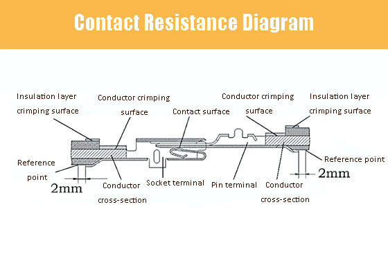
The terminal material mainly determines the inherent resistance. The quality of the crimping process controls crimping resistance. And the wire itself determines the resistance of the wire at the reference point. Pin terminal and socket terminal shrapnel in contact with the resistance generated significantly affects the terminal’s conductivity characteristics and temperature rise and should be given special consideration during design.
The positive pressure on the terminal depends on the elasticity of the terminal contact. This value is directly affected by the bend radius R and the cantilever length L of the tongue. It is important to consider these factors during the design process. Please refer to Figure 4 for the structure of terminal shrapnel.

V. Tail Crimping
The quality of crimping directly affects the transmission quality of terminals. The crimping engagement length and crimping height have a significant impact on the crimping quality. Tighter crimping results in better mechanical strength and electrical performance than looser crimping. So strictly controlling the crimping section’s dimensions is necessary. Many factors affect the crimping effect between the terminal and the wire. Each type of terminal has a certain range of wire diameters it can accommodate. And the wire diameter is an important factor influencing the crimping quality.
Furthermore, the wire itself is also worth studying. And the products at home and abroad have their different characteristics. In practical production, the following principles should be followed:
1. The wire diameter should match the tail end of the terminal.
2. The length of the stripped portion of the wire should be appropriate.
3. Select suitable crimping tools.
4. Conduct pull test after terminal crimping.
Test terminal crimp: test the crimp profile of the terminal and the terminal pull-off force. The profile can visually judge the effect of crimping. Crimping results shall not appear leakage of copper wire and touch bottom and other defects. Pull-off force can judge the reliability of crimping.
Based on the analysis of factors affecting the electrical performance of terminals mentioned above, it is evident that various factors influence the electrical performance of terminals. These factors include material selection during the early stages of design, the rationality of structural design, and subsequent product crimping, among others. Therefore, during the design process of such products, it is crucial to analyze problems from multiple perspectives and find the optimal design solution.
